This is an overview of one half of the optical navigation system I've developed for Georgia Tech eXperimental Rocketry (GTXR).
Aboard GTXR rockets are either Arducams or NoIR camera modules--simple, commerical-of-the-shelf (COTS) cameras connected to a Raspberry Pi. These provide a very cheap, simple sensor that can be used for absolute attitude determination.
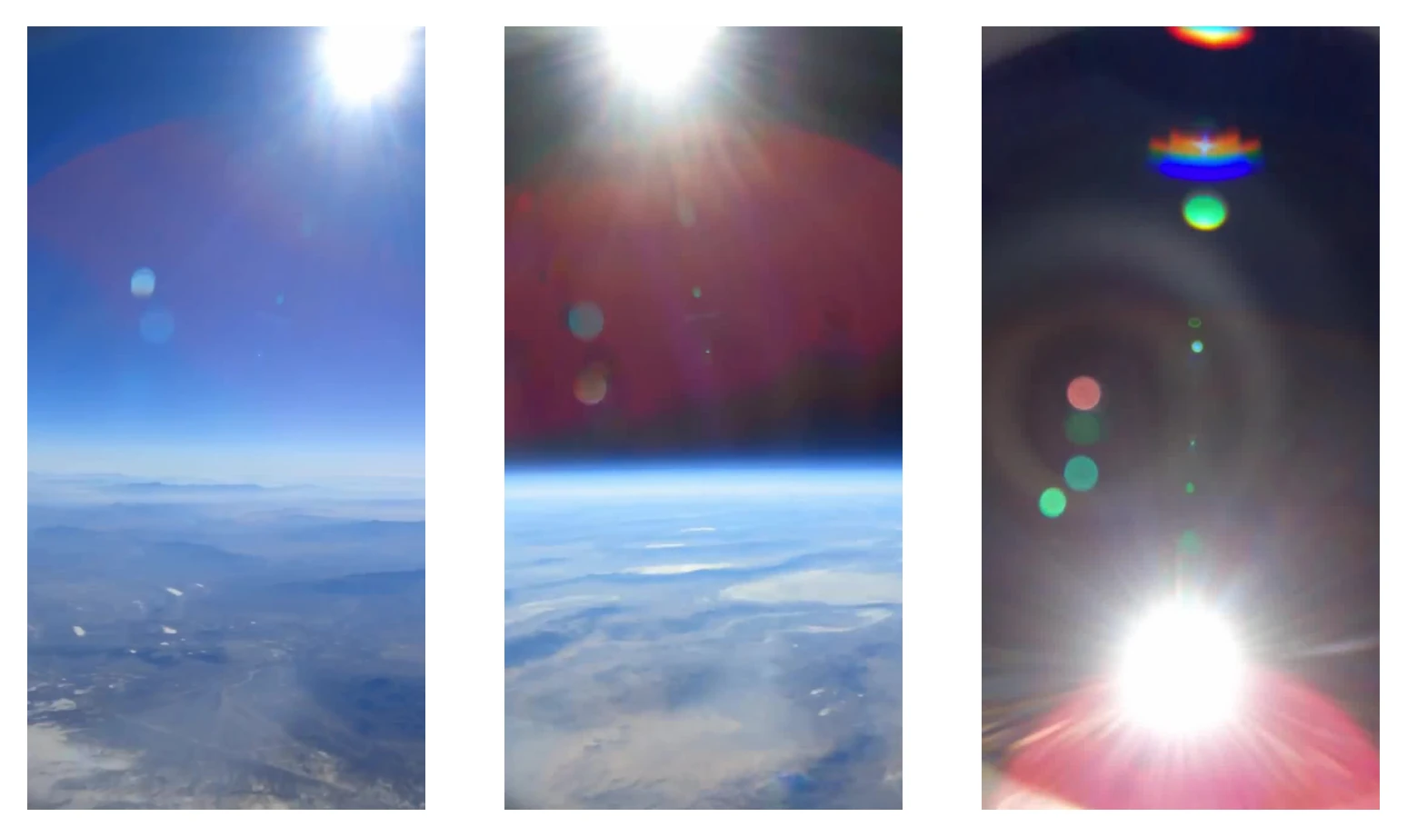
To achieve full attitude knowledge, two vectors to known bodies are needed. Classically, this was used for TRIAD attitude determination[0]. The sounding rockets launched by GTXR are suborbital, so the two most notable bodies in view of a simple camera system would be the sun and Earth.
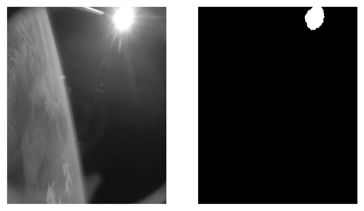
The sun is a pretty prominent feature in any image it's in--notably due to its brightness. These COTS cameras will automatically change their gain/exposure to avoid overexposure and underexposure. Thus, when the sun is in frame, the area it takes up has the highest brightness level in the image.
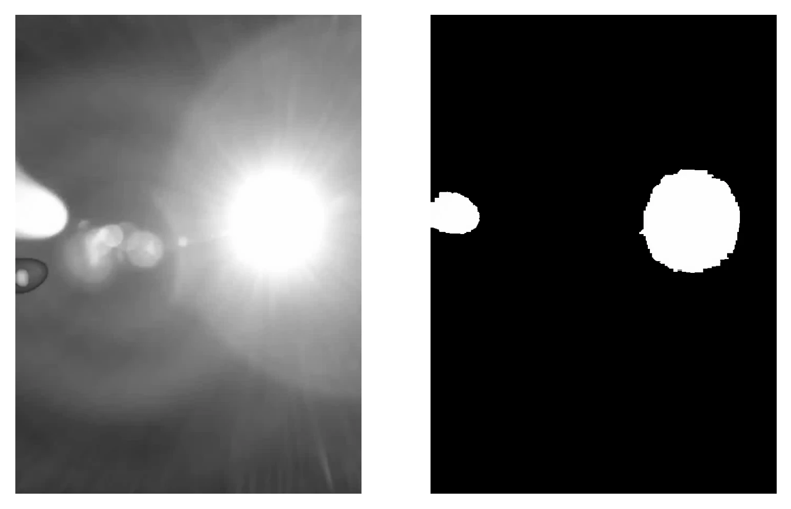
This is the first feature we utilize to isolate the sun: masking areas above a brightness threshold. The first step of this is turning the image from BGR (the default of OpenCV instead of RGB) to greyscale. Then, the image is thresholded using cv.THRESH_TOZERO (this preserves pixel values within the mask rather than resulting in a simple binary). In testing, thresholding at or above 250 seems to give good results. This step results in a mask of the original image only containing the brightest object(s) in scene.
Note that, due to camera auto gain, when not pointing at the sun, miscellaneous objects in the scene will pass this brightness check.
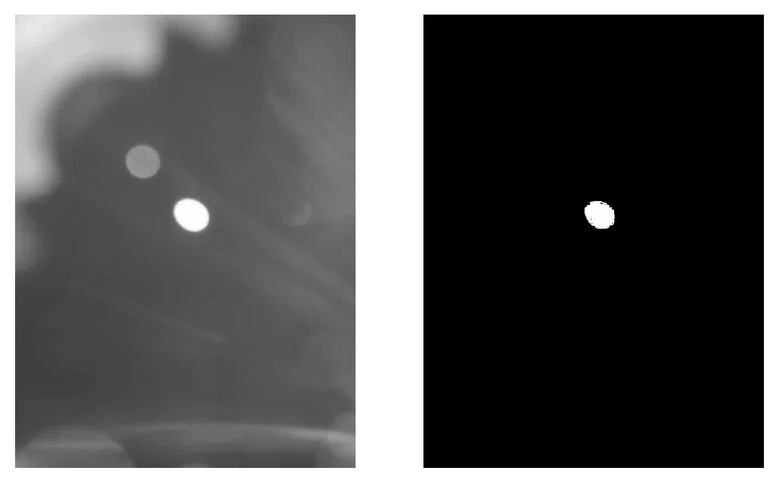
Thus, more checks are needed to ensure we avoid false positives. We want to err on the side of strict with these, as false negatives are acceptable--the Kalman filter onboard does not, by nature, constantly need measurements to estimate attitude. However, false positives will make our measurements far less reliable and therefore somehwat useless. There are two other notable features of the sun we can exploit here: (1) its size; and (2) its shape.
The more simple and boring of these is the size. Simply put, we can take the 00th moment to get the area of the mask and then check if that's above a certain threshold. If it is not, it's simply other phenomena caught in the mask due to the auto gain. This step filters out the lens flare caught in the mask in the above image--the area of the mask comes out to 508658.0 and the threshold (through testing set at 1500000) filters this out.
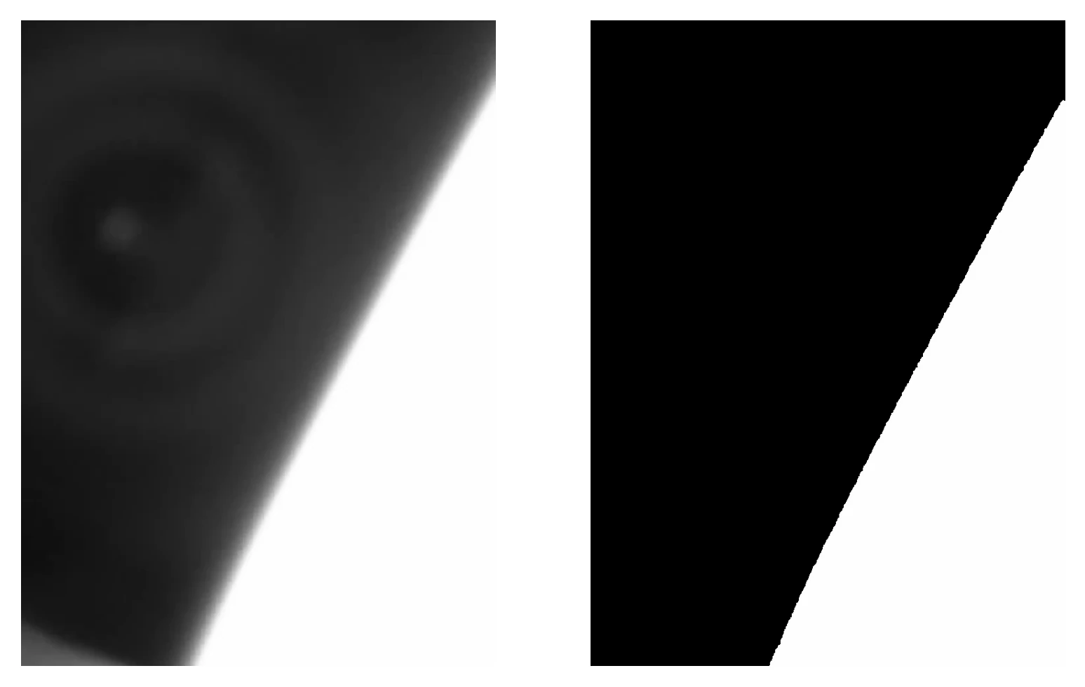
The much more interesting check is the shape. How do you quantify a shape? Not its size or location or orientation, but the shape in and of itself. The sun is a single roughly circular object so we only want to look for individual roughly circular objects. Our solution to this are moment invariants--polynomials built upon central moments that are invariant to operations like rotation, scaling, and translation. While Hu's[1] original seven moment invariants are flawed[2], they work well enough for our case.
| Moment | Sun Mask | Lens Flare Mask | Earth Mask |
|---|---|---|---|
| 1 | 6.51212292e-04 | 6.45181317e-04 | 1.04446426e-03 |
| 2 | 2.84763384e-08 | 1.68088555e-08 | 5.31536134e-07 |
| 3 | 2.09310572e-12 | 2.93606362e-13 | 4.74385304e-10 |
| 4 | 1.96272938e-14 | 7.54833466e-15 | 1.24995485e-10 |
| 5 | -3.90364689e-27 | 3.53360327e-28 | 3.01151875e-20 |
| 6 | -3.30168379e-18 | 9.64839788e-19 | 8.66488641e-14 |
| 7 | 7.66542491e-28 | -3.75755577e-29 | 4.41688503e-21 |
Note that for perfect circles, Hu's moment invariants go to zero. Thus, we are looking for moment invariants most near zero that have a maximum difference between the sun and Earth masks. This occurs at invariants seven and five, where the sun mask has a 7 order of magnitude lower result than the Earth mask. Note that invariant seven is one of Hu's invariants that was improperly derived--it is not rotationally invariant, but rather experiences a sign change under rotation. Due to this behavior, I've shied away from using it in this algorithm and instead rely on the fifth moment invariant. Thus, we have a metric we can use to determine if the shape bright enough and large enough is circular enough. In testing, objects that are not the sun have not dipped below 1e-21 in magnitude, thus it is used as the upper threshold for finally detecting the sun.
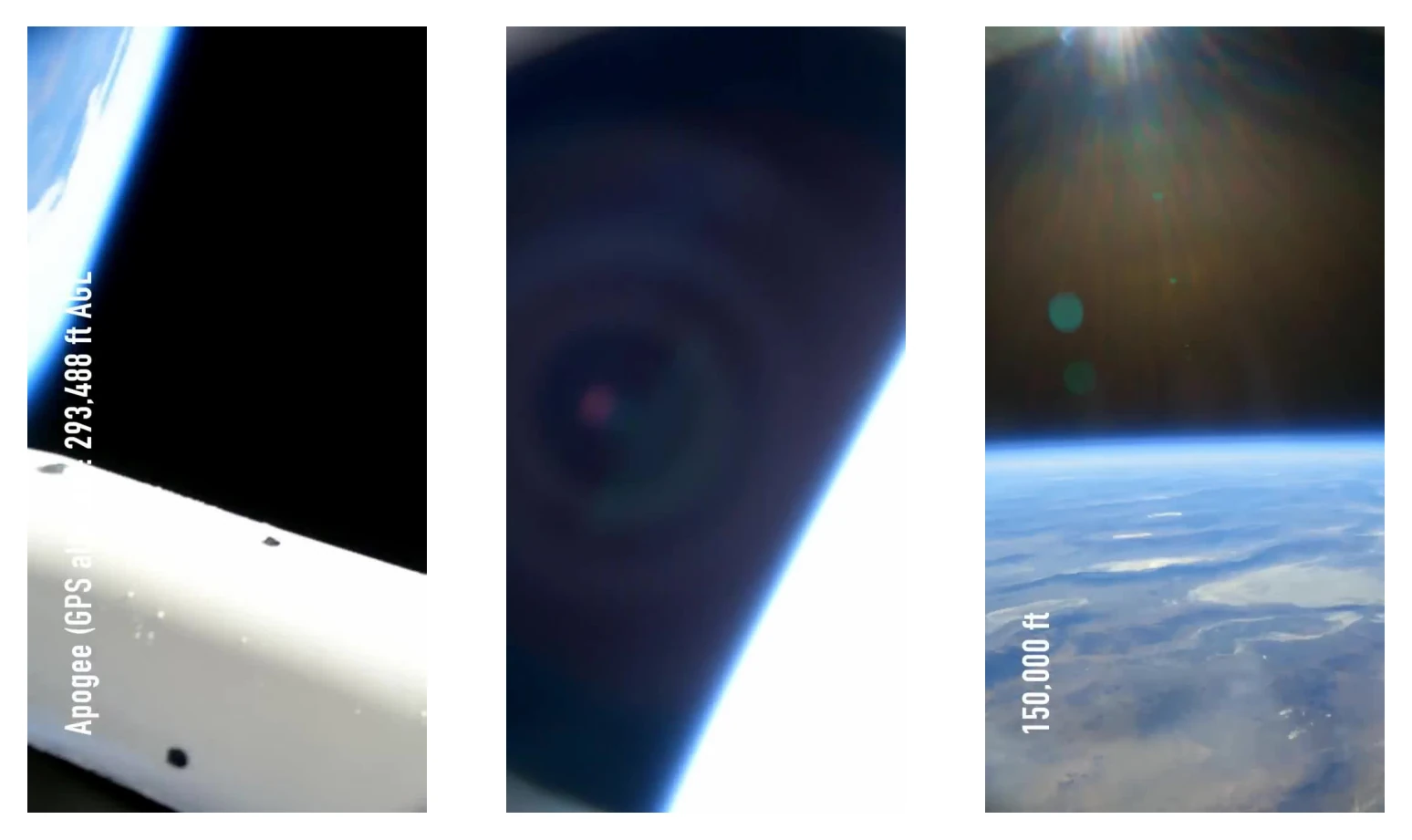
Using frames from videos uploaded by Kip Daugirdas (감사합니다 Kieran), I assembled a set of 27 test images: 16 that do not contain the sun but contain tricky, potential false positives and 11 that contain the sun but with features that could throw off the algorithm.
| False | True | |
|---|---|---|
| 0 | 10 | Positive |
| 1 | 16 | Negative |
I'm pretty happy with these results. A lot of these were pretty challenging images with the sun partially in frame, lens flare present, overexposed objects other than the sun, etc. The single false negative is a byproduct of the moment invariant filtering--a lens flare across the image was the same brightness as the sun resulting in a large moment and was labeled as not having the sun present. Other lens flare samples did not experience this and thus it seems like an edge case, potentially one that can be mitigated by hardware like filters or killflashes.
Given these results, it appears that the steps outlined above are a fairly robust method of sun detection and isolation.
While pointing a vector to the sun yields a much more precise attitude knowledge than simply detecting its presence, it's a very simple addition to this algorithm due to the method of masking we've used.
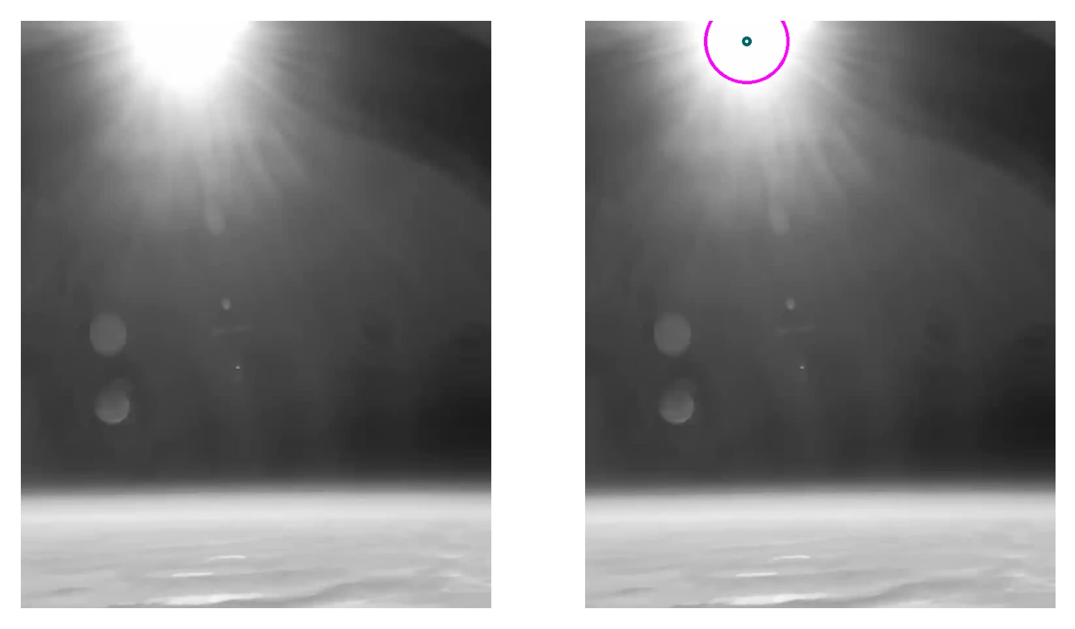
Since positive results are masks isolating the sun that retain the values present in the original image, the sun's location can be isolated by centroiding this mask. In OpenCV, this can be done for the x-axis by dividing the 10th moment by the 00th moment and the y-axis by dividing the 01th moment by the 00th moment.
cx = moments['m10'] / moments['m00']cy = moments['m01'] / moments['m00']There does however rise an issue where, if the sun is detected while only partially within the frame, the centroid is offset towards the edge of the sun most central in the frame. To solve this, we can have an alternate mode of detecting the sun's location when at the edge of the image.
OpenCV has a variant of the Hough line detection algorithm meant to detect circles in an image: cv2.HoughCircles. By constraining the minimum distance to be large (avoids multiple circle outputs) and setting appropriate values for the min and max radius for the circle, this function can be used to output the location of the sun by attempting to fit a circle to the partial circle present in the mask at the edge of the image. There are cases where the center output by cv2.HoughCircles is visually incorrect, so in this mode its result is actually averaged with the mask's computed centroid.
Now that the pixel coordinates of the sun have been found, pointing a vector to the sun is straightforward. So long as the incoming frames are undistorted (this can be done by cv2.remap with a precomputed set of transformation maps), a pinhole camera model can be used to directly transform from pixel coordinates to real world vectors[3].
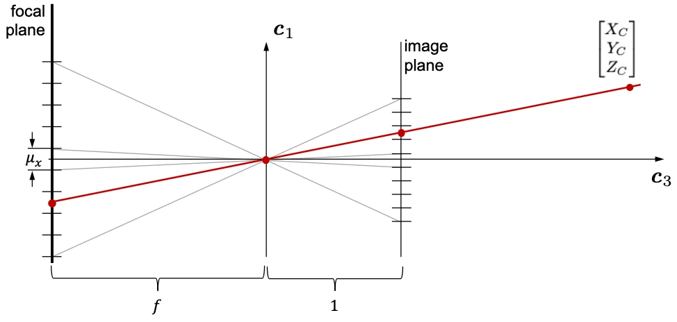
This model is based upon the camera obscura--a camera wherein no lenses are used, but instead light travels through a small hole and appears on the other side mirrored but otherwise undistorted. I will not delve into the derivation of the pictured model, but at a high level it involves breaking apart your imager components and assuming the captured images have experienced no distortion (hence the need for cv2.remap).
From this model, we can derive a coordinate transformation from the the image sensor at the focal plane to the real light passing through the image plane. This is expressed with the camera calibration matrix, \(K\),
$$ {K = \begin{bmatrix}d_x & s & u_p\\\ 0 & d_y & v_p\\\ 0 & 0 & 1\end{bmatrix}} $$
Above, \(d_x\) is the inverse of the instantaneous FOV in the x direction, \(d_y\) is the same in the y direction, \(u_p\) is the center of the image in x pixels, \(v_p\) is the same in y pixels, and \(s\) is the skew coefficient for the sensor (this can be assumed as 0 for a well built sensor). The inverse of this matrix can be taken to transform from pixel coordinations to coordinates on the image plane as,
$$ \begin{bmatrix}x\\\ y\\\ 1\end{bmatrix} = {\begin{bmatrix}\frac{1}{d_x} & \frac{-s}{d_xd_y} & \frac{sv_p - d_yu_p}{d_xd_y}\\\ 0 & \frac{1}{d_y} & \frac{-v_p}{d_y}\\\ 0 & 0 & 1\end{bmatrix} \begin{bmatrix}u\\\ v\\\ 1\end{bmatrix}} $$
These coordinates comprise the vector pointing from the object at the point in the image to the object in the real world in front of the camera. This completes the logic of THRASHER (THResholding And Sun Horizon EstimatoR) and the vector is given to the main flight computer to use in its Kalman filter.
[0] A Passive System for Determining the Attitude of a Satellite ^
[1] Visual Pattern Recognition by Moment Invariants ^
[2] Pattern Recognition by Affine Moment Invariants ^
[3] Optical Sensors: Images & Photodetectors, J. A. Christian, 2023 ^